01304 827609 info@use-ip.co.uk Find us

NVR not getting IP address from DHCP?

BHall

Member
Messages
11
Points
3
Hello,

I am having network problems with NVR-108MH-D-8P.

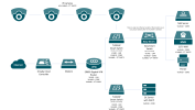
I have recently reconfigured our network to include multiple VLANs and reconfigured DHCP servers. The NVR used to be on the 192.168.1.x subnet and the IP address I set was static to 192.168.1.40. Now as I am planning to have the NVR set onto a new VLAN interface which is called 'Core Network' under VLAN10 and have it to reserve the IP address from the DHCP server as 192.168.10.30. The Core Network VLAN is controlled by a DHCP on a DC controller rather than the router (which is TP-LINK ER605).

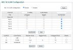
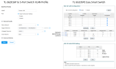
Currently the NVR is connected to a 5-Port unmanaged switch (I may have to consider changing this to a smart switch if this is the case) along with my NAS and printer, both of these devices are also connected to the same VLAN which is controlled by TP-LINK Omada and it is connected from a single port on TP-LINK TL-SG2016P smart switch.

When I went to change the network settings on my NVR to DHCP, it randonmly gives an IP address with 192.168.1.168 which to me looked incorrect, particularly with the NVR being on VLAN10. I could not connect to this IP address as the automatic configuration also gives the gateway as 1.0.0.0 which is unusual. So I thought of looking at setting static on the NVR to the IP configuration I wanted it to be and then it picked the NVR through the network but does not show the IP address I set it to, which to me is very frustating.

I've looked at the IPv4 setting in Expert mode and changed this, but comes back with the conflicting IP warning. It seems this only works with two default IP addresses I believe which they are: 192.168.254.1 and 192.168.253.1

So either this appears to be an issue with the NVR firmware or it is my network configuration.

Please could you give me some assistance on this, it would be greatly appreicated.

Many thanks,
Ben
 
Your unmanaged switch is not supporting IEEE 802.1Q (aka VLANs). Your switch needs to supports VLAN tags for your design to work.

None of your devices (NVR, printer, etc.) will understand VLAN tags, thus for things to work as you've designed:
  • a VLAN capable switch will need to be configured to add or delete the VLAN tag whenever a network packet enters or exits an "access" port on the switch.
Your unmanaged switch won't permit this. You are unable to assign a port to a VLAN. Thus you are at an impass.

Another way to think about it, your current switch will only understand untagged packets so, by default, EVERY packet flowing thru EVERY port is on the same untagged VLAN.

What your router and this other DC controller supports is a mystery to me.... so you'll need to figure out what kind of support they have for IEEE 802.1q. Probably none, but ???

Some options you might consider:
  • re-design your network to "physically" separate your NVR etc. from other devices
  • obtain network equipment that will support IEEE 802.1q
  • or some of both
Draw & provide a detailed diagram of what you're trying to do, if you'd like better answers. HTH.
 
Hi Sportster,

Thank you for responding to my thread.

I do have another switch which is the TL-SG105PE which has VLAN capabilities and when I tried setting this up by configuring the main port to the infrastructure VLAN (VLAN1) which has the 192.168.1.x subnet, this allowed me to access the interface of the switch to configure the VLANs but I can't seem to get the devices set onto VLAN10 like I have configured it on the actual network configuration itself, so I swapped it back to the unmanaged switch where I managed to have my NAS and printer working fine.

So I may be able to have another go at configuring this switch.

I have found out that the ER605 router does in fact support IEEE 802.1Q but from the DC server, it does it's job giving out DHCP to clients I reserved through this way and this seem to work fine so I'm assuming it does too, but cannot confirm if it actually supports it or not after doing some research.

I'll look at producing a network diagram as this is something I needed to do anyway, so I'll put this on here when I have managed to do one.
 
Just a heads up..... I'm not familiar with TP Link's implementation of VLANs.... but I just read a TP LInk manual on it (I'm more familar with Cisco's IEEE802.1q). Seems TP Link has 3 possible implementations of VLANs..... Multi-Tenant, Port Based, or IEEE802.1q. In addition to the network diagram, we need to be on the same page with the implementation you've employed (& which one you want)..... Multi-Tenant, Port Based, or IEEE802.1q ?
 
Hi Sportster,

I would be using the IEEE802.1Q as this will be the case across the network.

I have made a simple network diagram with the hope of it being clear to understand. As you would see that I prefer to have the cameras on a different VLAN but I will be putting a rule in place to allow the cameras to communicate with the NVR which would be on VLAN10, hence VLAN40 is being added from the Smart Switches to the NVR.

On the TL-SG105PE switch, I have made the following configuration but it isn't giving an IP address when the switch itself is on VLAN1. My NAS and printer also does not get an IP address as the single Ethernet port connected from SG2016P switch when it is set as VLAN1, so clearly there is something I am unsure what I'm doing here.

I hope this helps.
 

Attachments

  • NetworkDiagram1.png
    NetworkDiagram1.png
    206.3 KB · Views: 60
  • SwitchConfig1.png
    SwitchConfig1.png
    65.8 KB · Views: 53
Some observations, in no particular order, that may help (or not):
  • TP-Link may have a lot of capabilities I've not familiar with, so be sure to do your own research to ensure you're configuring your network using best practices. aka some of my thinking may be wrong.
  • Assumption..... all your switches are L2 switches. None are providing any L3 functions. In your network, L3 is done only at your router.
  • The NVR, with a single interface, can't be privy to "BOTH" VLAN10 & VLAN40 using traditional firmware from Hikvision. It's one VLAN or the other. Other vendors may provide Linux software that understands the VLAN tag in the IP header, but HIK does NOT.
  • Going forward, you might want to consider getting a newer NVR with 2 interfaces.... thus allowing one interface on VLAN10 & the other interface on VLAN40.
  • Port 5 looks like your TRUNK port. Port 5 MUST BE TAGGED for ALL intended VLANS. In your case, both VLAN1 and VLAN10. Modify your configuration to support VLAN1 "AND" VLAN10 tagging on Port 5.
  • VLAN40 traffic will never reach this (5) port switch. This is correct given your configuration. The bad news is ALL VLAN40 traffic will have to be routed thru your router. Your gateway router will need to copy VLAN40 frames over to VLAN10 and vice versa. That might become a bottleneck in your network..... time will tell.
  • The PVIDs for your switch are not shown. I guess the PVID was set to VLAN10 on Ports 1,2,3. And PVID = VLAN1 for Port 5.
  • VLAN1 traffic will reach this switch, but will be dropped from reaching Ports 1,2,3. This is fine.
  • A typical DHCP Server is limited to a single Broadcast Domain.... which equates to a single VLAN. A DHCP Server on VLAN10 can respond to ports on VLAN10 only. I assume you may need to move your DHCP Server over to VLAN10. Or add DHCP Servers as needed.... your router may be capable of providing a DHCP Server function on multiple VLANs... but I'm unaware of your router's full capabilities.
 
Last edited:
Hi Sportster,

Here are the answers to your observations:
  • I have been doing a lot of research into this but I think by the sounds of me doing this may complicate things but at least I'm learning from it.
  • The switches and the router I assume are L2 compatibility, don't think they'll have L3.
  • I did originally think of doing this but given it to be working under a single interface, I've decided to have the NVR on VLAN1 (although it it not ideal for me in my networking situation). I've managed to eventually get NVR which is connected onto Port 2 of the 5-Port switch onto VLAN40 but it is still not giving the IP address from the DHCP which VLAN40 is managed by the router and not the DC server.
  • I did consider having CCTV integrated into my Synology NAS and this option to me remain to be open for consideration but the downside is licensing and it'll cost money.
  • You are correct, Port 5 is the Uplink port (or Trunk) and I have tagged this on VLAN10 & VLAN40. Other ports I've tagged on VLAN40 were 1 & 3 when these were on VLAN10.
  • It'll be good have VLAN40 working correctly for the cameras (possibly NVR too) so they're all on the same subnet with DHCP coming from the router, so routing might help all VLAN40 traffic to the switch.
  • I have now included a picture of the PVIDs but given the difficulty of giving an IP address when it was on VLAN40, I've changed the PVID for Port 2 to 1. Now it's decided not to give an IP address even when it's on VLAN1.

Given the complexity of this, I am now looking just to keep everything simple wherever I can but having the advantage of using the VLAN to keep my network secure.

I have included some pictures of my recent configuration and bearing in mind that the cameras are still under the old VLAN1 and they have not been moved since I've reconfigured the network last week, so I can still access these. As for the NVR, this is now back on VLAN1 but can no longer access the interface with it being connected to the 5-Port Smart Switch (TL-SG105PE) which is then connected to the TL-SG2016P switch as the main switch. I can access my NAS and printer correctly now after this recent configuration.

I hope this all helps.

Best regards,
Ben
 

Attachments

  • NetworkConfig.png
    NetworkConfig.png
    377 KB · Views: 49
From my vantage point, the problems you're encounting are 3-fold:
  1. VLAN1 packets are currently travelling "untagged" in your network creating the mass confusion you're in.
  2. the DHCP Server you have on "EACH" VLAN. You'll need to sort your DHCP Server(s) out once you fix your VLANs.
  3. "untagged" packets traversing the TRUNKs between ALL your switches.
To maintain your sanity, NEVER/EVER send untagged packets across ANY TRUNK. You need to fix your config to follow this golden rule. Failure to adhere to this will drive you nuts.

See attached PDF for a suggested configuration. The bogus VLANs 999 & 998 are there to prevent VLAN tags from being stripped and to prevent any untagged packets from traversing the TRUNKs. If untagged packets make it into your TRUNKs, they go into a black hole.

Should my suggested config not work, you've exhausted my knowledge on TP Link switches. So, in advance, my apologies. Probably best if you move your question(s) over to the TP Link Community at --> TP-Link Community

HTH.
 

Attachments

  • Suggested VLAN config.pdf
    72.6 KB · Views: 85
Hi Sportster,

After all this time, I've figured out that I've had the Ethernet port of the DVR was plugged into one of the POE ports which is why it wasn't getting an IP address after all! I've got it to connect to VLAN10 but when I went to reset the system because I was that frustrated, all the IP cameras are now changing to VLAN10 but I reckon as NVR only has one Ethernet interface it probably cannot do multiple VLANs like you have mentioned.

So having said that, I've decided to isolate the NVR onto VLAN40 along with the rest of the cameras and just keep it under the same VLAN.

Your configuration does seem to work although I don't have a 100% understanding of VLANs which is why I'm learning with all this, so I'm assuming its more secure and possibly "isolated" against other VLANs. I've noticed the switch IP address keeps changing but if I set it on static, I might lose the interface so don't want to risk resetting the switch and setting it up again.

Thanks for your help with this by the way, this was quite challenging.

Ben
 
A few thoughts:
  • having the NVR plugged into the wrong port, doesn't help. Good you have that sorted now.
  • isolating your cameras and NVR on VLAN40 would seem to make sense to me. Anyone trying to access VLAN40 has to go thru your router. And your router has the opportunity to permit or deny access to VLAN40 (assuming your router has Access Control Lists or the like).
  • remember the golden rule....... to maintain your sanity, NEVER / EVER send untagged packets across ANY TRUNK. Failure to adhere to this will drive you nuts. The suggested config I provided earlier attempts to implement just that.
  • there are ways to deal with your switch address changing. Since DHCP is (most likely) the default for the switch, then:
    • verify the switch is on VLAN1..... AFAIK, TP-Link seems to enforce this. (dumb design by TP-Link, IMHO, but it is what it is)
    • find the 12 byte MAC address of the switch
    • go to the DHCP Server for VLAN1 and find the "DHCP Reservations" section (aka "MAC Bindings") and set up an IP address for that MAC address. Going forward, each time the switch is reset it will get whatever IP address you have set in this table.
The above is my personal preference. I use DHCP Reservations for my cameras & NVR too. Takes a few extra minutes to set up, but once done it's done.
OR
you can always skip the above & just use static IP addresses (and manually maintain a list of what's been assigned).

Of course, do whatever works for you. HTH.
 
Back
Top