01304 827609 info@use-ip.co.uk Find us

Wiring a motion detection on a DS-7208HUHI-K2/P DVR

old codger

Active Member
Messages
39
Points
8
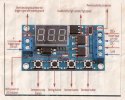
Does the DVR use its own low voltage supply when a motion warning is triggered, asking this before connecting an outside 12v supply to the alarm in plug on the back of the DVR.
Also how do you separate a second alarm warning on the same screen?

cctv-alarm.jpg


motion-lines.jpg
motion-lines.jpg
 
@old codger alarm inputs usually expect an open or short circuit from a dry contact like a door open / closed switch. Voltage inputs connect to the DVR relay contacts, I can't see any in your pictures.
You could use the +12V to energise a relay coil and then connect a relay contact to the alarm input. What device are you trying to connect to the alarm input?
 
Thank you for your reply, I will explain what I am trying to achieve.

I could use "line crossing" in place of "motion detection", and when say rule 1 is crossed it triggers alarm ports one in and one out on the DVR with a 'N' feed from an outside 12v supply for say 5 seconds. Rule 2, doing the same with the 'P' supply.

These two feeds then used to trigger a timer, without too many faults’ alarms.

Sorry for the delays, being in my nineties, I am not that quick at things.
 

Attachments

  • timer.jpg
    timer.jpg
    111.2 KB · Views: 148
It sounds like you're trying to get the DVR alarm activation - line crossing/motion to enable a PIR. It is possible but it may be a bit of a faff with the wiring as the alarm input for the PIR trigger that your going to enable using the alarm output triggered by the motion/line crossing share a common ground connection (I believe)

If you're considering using a PIR anyway, my advice would be to use that solely (without combining it with the DVRs analytics) as it will give very few (if any) false alerts so long as you use a decent PIR. I use the GJD Opal Elites and have done for years. Just supply it with 12V DC and wire the common/normally closed connection back to the DVR and connect it between GND and one of the alarm inputs. The GJD models allow you to set sensitivity, pulse count, range, duration of trigger etc.
 
Last edited:
I would still like to know if the DVR generates it own low voltage output, as I do not want to damage anything by introducing an outside 12v supply to the ‘in’ alarm port on the back of the DVR?
 
Hi @old codger

Based on our research and looking at YouTube videos about connecting Alarm devices to a DVR, all the devices from these demos have used separate 12v PSU which suggests the DVR has no substantial voltage output from the alarm I/O terminals.
 
I would still like to know if the DVR generates it own low voltage output, as I do not want to damage anything by introducing an outside 12v supply to the ‘in’ alarm port on the back of the DVR?
my E series 7604 NVR has +5Vdc on alarm inputs 1 to 4.
 
@old codger from my days in electronics there may be a resistor in series with each alarm input to limit the current. I would not connect an external voltage to my alarm inputs.
 
We are getting a 4.7v suppy from the DS-2708HUHI-K2/P DVR'S without putting any external supply in, which does not trigger the timer, yet 3 x 1.5v batteries will. Would the 4.7v supply feed a 3.3v reylay, to work the timer?
 
We are getting a 4.7v suppy from the DS-2708HUHI-K2/P DVR'S without putting any external supply in, which does not trigger the timer, yet 3 x 1.5v batteries will. Would the 4.7v supply feed a 3.3v reylay, to work the timer?
I'd say not. That 4.7V won't have enough current to drive anything.

I'm not quite sure why you need the timer at all to be honest. If your PIR was 12V DC and can be set to normally open operation (going closed circuit in alarm), you can set the motion detection/line crossing to trigger output 1, set the timer of output 1 to be 5 secs or 10 secs for your timer. The PIR would then only hit the alarm input during the period following the motion detection/line crossing. Something like the diagram below - excuse the scrawl:

IMG_2936.JPG
 
We are getting a 4.7v suppy from the DS-2708HUHI-K2/P DVR'S without putting any external supply in, which does not trigger the timer, yet 3 x 1.5v batteries will. Would the 4.7v supply feed a 3.3v reylay, to work the timer?
Is the 4.7V being pulled down when connected to the timer? if it is the timer is trying to draw more current than the 4.7V can supply. The series resistor I mentioned earlier could be dropping the voltage. The batteries work as there is more current available.
the 3.3V relay may work but there may not be enough voltage / current to drive it.
 
This to me suggests that this DVR is not up to doing what we want it to do. The biggest gripe I have, is that it shows our Alarm warning in and out box at number 13 on the back view of the DVR, but no manual we have been abel to find has any instructions on its use.

Time I think to look at other makes of DVR’s?
Full instructions for the Hikvision NVRs and DVRs are available online but tend to cover more than one model. Because they have to cover every feature and use case they are also rather in depth and several hundred pages. I guess that's why the recorders come without them. There are multiple uses for the alarm inputs and outputs such as connecting a door contact or PIR to trigger an input, or using the output to trigger a floodlight via a relay or an external sounder when an event occurs. Setup is relatively straight forward. As I alluded back in post number 7, your use case (if I've understood it correctly) is a little unusual. Combining a PIR and timer to the DVR motion detection, to cut down on false alerts seems unnecessary, when just using a PIR alone would eliminate them completely. I'd describe it as a bit Heath Robinson - an overcomplicated solution to a simple problem (that problem being that the DVR motion detection is overly sensitive)

To trigger an alarm input a wire pair is connected between your device and the alarm input and G terminal. The device will either connect those two terminals when it activates (normally open) or disconnect them from one another (normally closed). The actions that take place when that input activates are set in the DVR menu.

It is absolutely possible to achieve what you're trying to with that DVR. The features available on other models with regard to alarm inputs and outputs won't differ substantially from what you have. Depending on the model of your Hikvision HDTVI cameras, you may find that they will not work with another manufacturers DVR (as HDTVI is a proprietary Hikvision technology)
 
Last edited:
Will you please send me a link to a manual that describes the in out warning feeds, for our DVR.

As all we want is a between 3 to 15v signal from the DVR, to trigger our independent alarm system.
 
Will you please send me a link to a manual that describes the in out warning feeds, for our DVR.

As all we want is a between 3 to 15v signal from the DVR, to trigger our independent alarm system.
If you have an independent alarm system just connect a pair of wires between G and output 1 on the DVR then connect them to the zone in the alarm panel. Set the alarm output in the DVR menu to Normally Closed operation with a 1 or 5 second timer. Then set your line crossing or whatever event to trigger the alarm output in the actions. When the alarm system is armed and an event occurs on the DVR, the output will open triggering the zone - no voltage is required.

Edit: Manual attached
 

Attachments

  • UD12108B_Baseline_User-Manual-of-Turbo-HD-Digital-Video-Recorder_V4.20.100_20181107.pdf
    8 MB · Views: 225
Last edited:
Our DVR was set to your instructions above apart from changing the NO to NC box, we have rectified this but when the line crossing is triggered it still only sounds the alarm in the DVR without triggering our independent alarm system.

Which to me indicates we need a RS485 itrface or relay, between the two units?
Not at all - you shouldn't need either for a conventional alarm. What alarm panel is it that you're connected to? There are a couple of steps to check:

  1. For your line crossing ensure that the checkbox for "linkage method" is enabled for alarm output that you've used as in the picture below A > 1
  2. If you've already done the above - connect a test meter to the wires you've taken to your alarm panel and set to continuity. You should see only a couple of ohms resistance (depending on the length of the cable) To confirm that the output and configuration are correct - trigger a line crossing, you should see the test meter change to infinite resistance when you hear the alarm from the NVR. If not something is wrong in the configuration.
  3. If you do see the change of state from closed to open circuit on the wires all is good and the issue is with the connection to your alarm system. If you've just connected to a spare zone, then the input may need to be enabled from the engineers menu of the alarm. If you're wanting this to trigger even when the alarm is not set then the zone will need to be programmed to the correct type (tamper, 24 hour)
 

Attachments

  • Screenshot 2021-03-21 at 18.27.55.png
    Screenshot 2021-03-21 at 18.27.55.png
    105.8 KB · Views: 142
Back
Top